
Intersection of Solids
|
This is a common exam question and can be quite satisfying to do. It has appeared as both a short and long question.
A question is generally broken up into 4 main parts:
|
|
Terminology
Apex - the pointy tip of a pyramid or cone
Bend Points - when a line of interpenetration meets the edge of one of the shapes, it turns. The point on the edge where this happens is bend point.
Intersection - one solid going through another
Line of Interpenetration - the edge where the solids meet, this is what we're trying to find
Orthographic Views - Elevation, Plan or End View
Typical Exam Question
Always label your points - it makes things much easier!
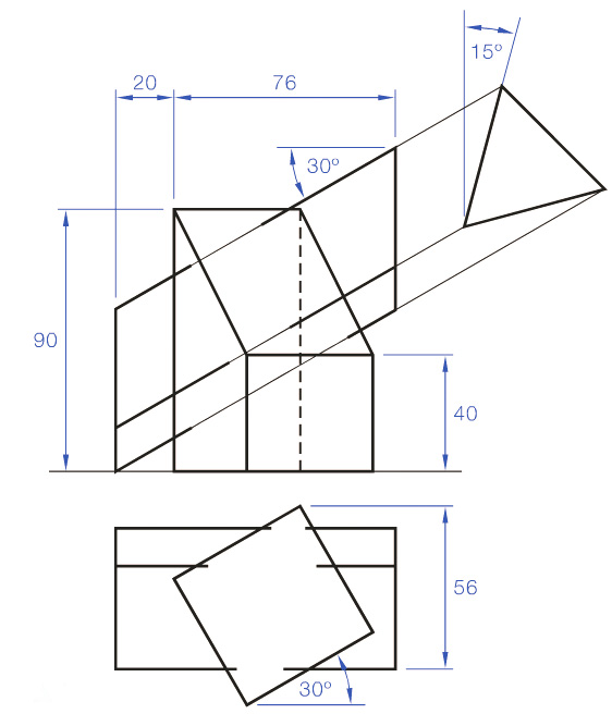
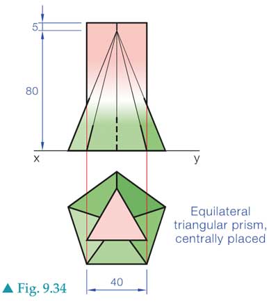
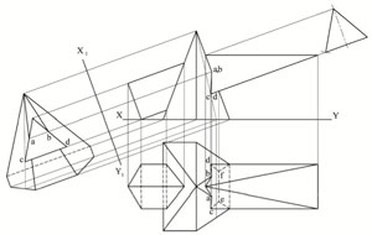
The example below is a worked example from Graphics in Design & Communication, p186
The example below is a worked example from Graphics in Design & Communication, p186
1 - Draw Plan and Elevation
|
|

2 - Auxiliary View or Section Planes?You need to decide whether you're going to use section planes or an auxiliary view. It can often be done with both but auxiliary works well if there's a prism at an angle. The steps below are for an auxiliary view.
|
|
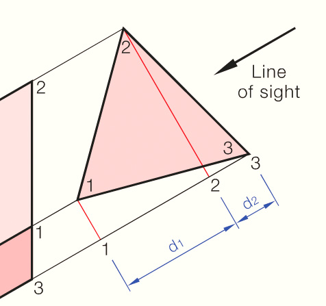
3 - Find Corners
|
|
4 - Find Bend Points
|
|
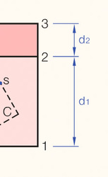
5 - Plan
- There are often several points that are quite obvious in plan view
- Find these and project back to the elevation
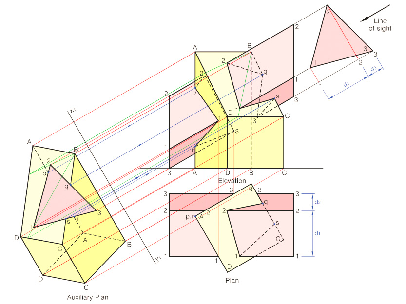
6 - Completion
- Write out the sequence of the corners and bend points, then follow that sequence to complete the lines of interpenetration, including hidden lines.
- It can be helpful to use the plan to figure out what's a hidden line
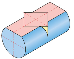
Method 1 - Limits
|
|
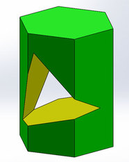
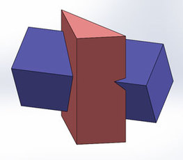
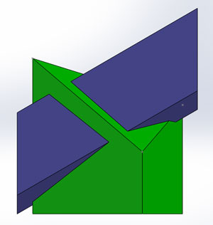
3D Models for Worked Examples
|
|
|
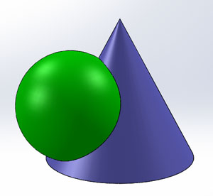
Method 2 - Radial Elements
|
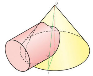
|
3D Models of Worked Examples & Questions
Method 3 - Horizontal or Vertical Section PlanesThese methods are listed separately in your textbook but the idea is the same with both so they are considered together here.
|
|
3D Models of Worked Examples
Tip: Use the Section Plane feature in Solidworks to quickly see what the different section planes look like.
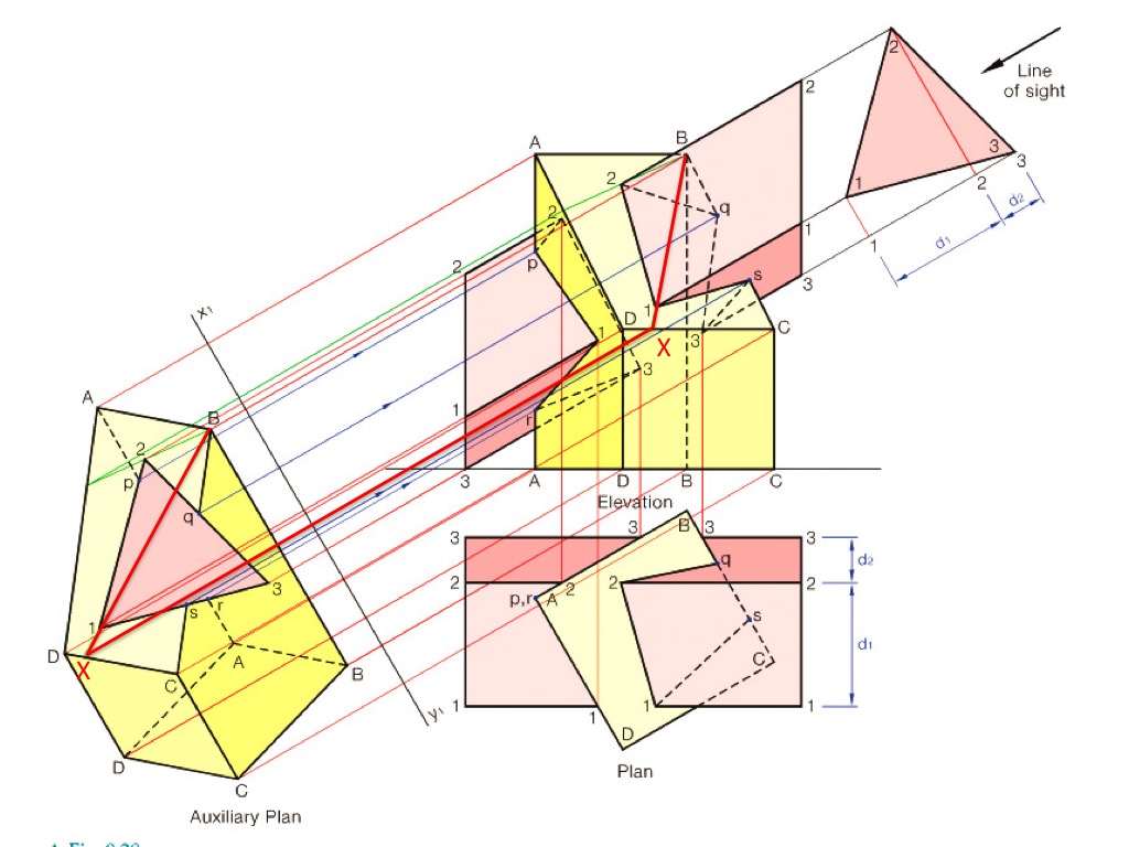
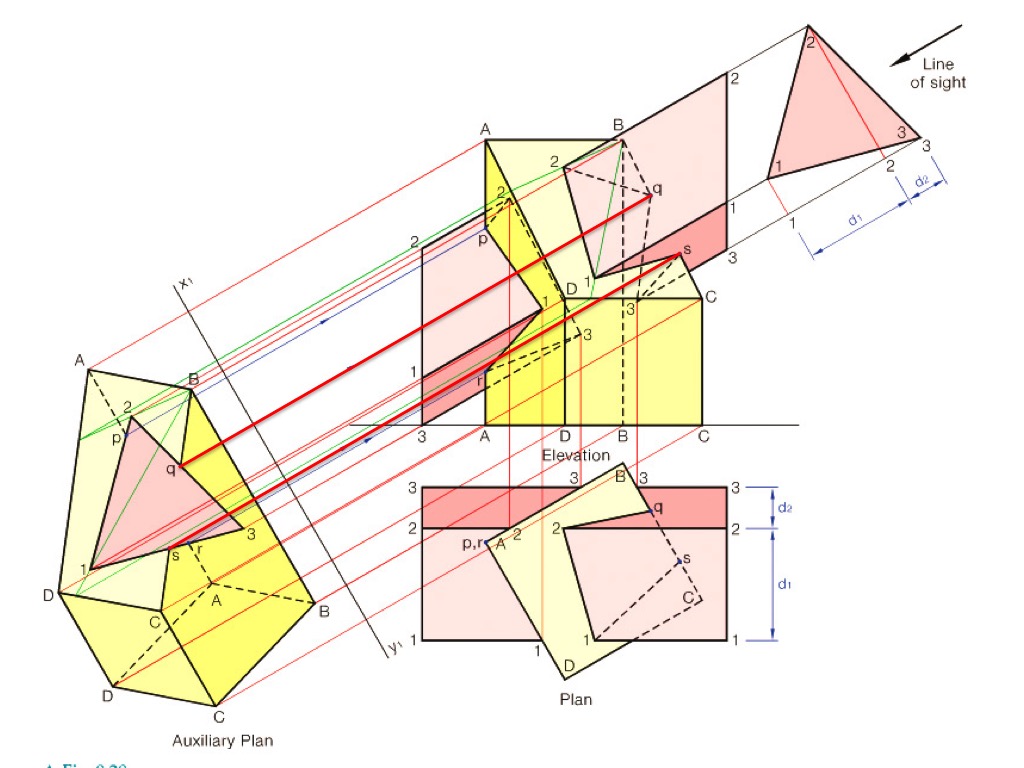
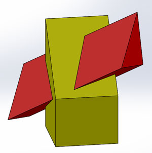
Method 4 - Auxiliary PlansThis method is the most common in exam questions so make sure you know it!
|
|
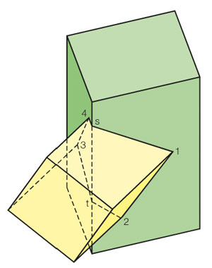
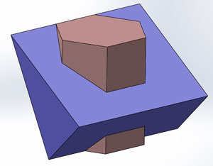
3D Models of Worked Examples & Questions
|
|